Unexpected output when using usePOLYLINE with DXF exporter
I'm seeing an inconsistency in the output of the DXF exporter between having usePOLYLINE enabled and disabled. I'm in the process of reducing a reproducible case to the point where looking at the generated DXF text is manageable; but I thought I'd share what I have now.
To reproduce:
- Run the following in a Maker.js playground:
var makerjs = require('makerjs');

function polylineBug() {
  var pathData = `
    M48,30 L50,30
    M50,15 L50,20 Z
    M50,25 L55,20 L50,20 Z
    L50,30
  `;

  return makerjs.importer.fromSVGPathData(pathData);
}

module.exports = polylineBug;
- Export as a DXF via button beneath model view. Enable the Use POLYLINE option, and choose Max accuracy. (Bug appears to happen on any accuracy.)
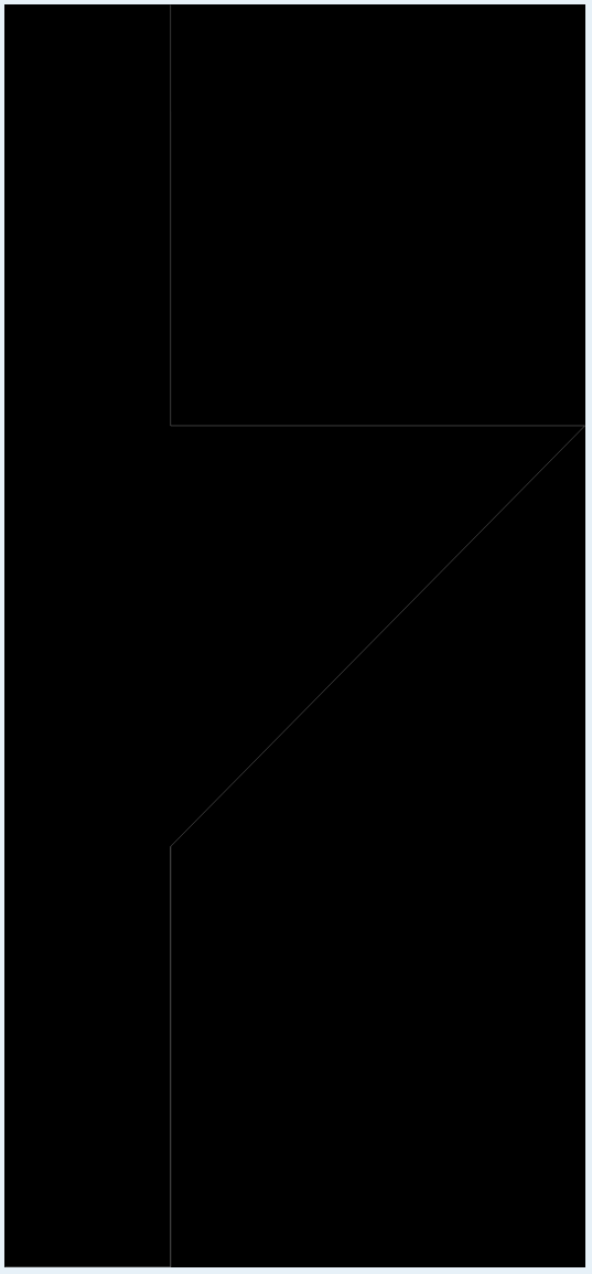
Here's what I'm seeing in the exported DXF with POLYLINEs enabled. Note the missing segment on the left side of the triangle:
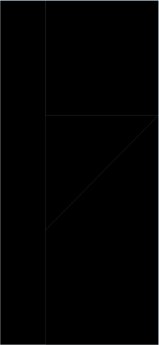
Here's a DXF of the same model, exported with Use POLYLINE disabled. The segment on the left side of the triangle is back:
Some other interesting values for pathData which do not trigger the bug:
M48,30 L50,30
M50,15 L50,20 Z
M50,20 L55,20 L50,25 Z     // reversing the direction of the problem triangle
L50,30
M48,30 L50,30
M50,15 L50,19 Z     // breaking the chain between y=19, y=20
M50,25 L55,20 L50,20 Z
L50,30
From fiddling around with values in pathData, it seems like the bug is not triggered when the chain including the segments at x = 50 is broken. (Uncertain if this would be considered a real "chain" in Maker.js's terminology – I'm realizing that I should read through the chain documentation.)
Hi David, you've hit a fundamental principle of the chain algorithm: that there cannot be more than 2 paths occupying the same point. This should probably be better documented. When the algorithm arrives at a point where there are 3 (or more) paths, it will follow one of them in a non-deterministic way 🤔. It just doesn't "know" which one to follow. Perhaps it could be passed a callback, asking for a hint. Otherwise we would be introducing a lot of computation.
Breaking down your path data:
M48,30 L50,30 - create a line from 48,30 to 50,30. So far so good.
M50,15 L50,20 Z - create 2 lines: from 50,15 to 50,20, and (Z) a line from 50,20 to 50,15. This is, in and of itself, already an endless chain. At this moment there are 2 paths at 50,20.
M50,25 L55,20 L50,20 Z - create a triangle. The 2nd and 3rd lines also sharing 50,20, which makes 4 paths on the same point. Also, the first and 3rd line share 50,25.
L50,30 - create a line from 50,25 (the previous Z) to 50,30. Now there are 3 paths sharing 50,25.
If you can isolate the triangle commands M50,25 L55,20 L50,20 Z, to create a model separate from the other commands, you can add a layer property to that model. The chain algorithm will honor a layer as a boundary. Then this triangle will be a chain when you export.
Thanks @danmarshall – that makes sense.
Unfortunately, manually separating the chains in my models won't work for my application, which is dealing with user-generating paths. Do you have any advice for how to deal with this on a more general basis? Or any terms I could use to search for more info? (Unfortunately, "cad model chains" is a polluted query...)
In case it helps someone else coming to this issue: so far, I've tried:
- Separating the input SVG paths into their closed subpaths, and importing each into a separate layer. This fixes a lot of the issues, but a subpath can contain multiple coincident points within itself.
- Preparing the SVGs by converting them to absolute commands; walking each closed subpath of the SVG paths, keeping track of which absolute points have been used as an endpoint for a command; and when a command repeats an endpoint, nudging the endpoint a very small amount in a different direction until collision is avoided. This seems promising, but I'm getting stuck at importing the SVG paths after converting them to absolute paths: I've tried these two utilities to convert the path strings to absolute coordinates, which looks fine in the generated SVG files; but importing them into Maker.js via
fromSVGPathDatagives me messy, wobbly models.
Some things that I think I should still try:
- Nudging the endpoints like in (2) above, but modifying the original SVG commands.
- Looking for colliding endpoints in the Maker.js models generated from
fromSVGPathDataand nudging those out of collision. I'm not certain if this would work – my understanding is that, at that point, the chain explicitly defined by the pen movement in the SVG path string has been lost. (As in, it would be tough to answer: If I move endpoint b of curve (a, b) to b', should I move (b, c)'s endpoint or (b, d)'s endpoint to keep the chain from breaking?)
Hi David, sorry I've been away from the computer. Also I don't have a solution straight away so I've been thinking about how to solve this.
First, I can probably add an option to fromSVGPathData which could output the chains directly from the SVG path commands. This would give you an array of chains, which would be delimited by the M and Z commands.
The second part is tougher. Here you would want to pass chains into the DXF export function, instead of letting it find them for you. I can probably make it so it accepts mixed types of data as input, instead of just a model.