InteractiveCrossingMinimizer fails because InternalProperties.ORIGINAL_BENDPOINTS isn't transformed
GraphTransformer doesn't transform some properties, i.e. ORIGINAL_BENDPOINTS which is used for placing the edges with the interactive crossing minimizer. This leads to the edge layout to go completely haywire for most of the layout directions.
Do you have an example graph that reproduces this problem? Preferably create and liked from elklive?
I suppose since the original bendpoints are an internal property nobody considered doing this. Since this looks like an easy fix, we might be able to fix this for ELK 0.9.0.
After learning the syntax from the xtext definition I was able to produce an example:
//algorithm: fixed
algorithm: layered
elk.direction: DOWN
cycleBreaking.strategy: INTERACTIVE
layering.strategy: INTERACTIVE
crossingMinimization.strategy: INTERACTIVE
nodePlacement.strategy: INTERACTIVE

node n1 {layout [position: 0,0 size: 50,50] ^position: "0, 0"}
node n2 {layout [position: 0,200 size: 50,50] ^position: "0, 200"}
node n3 {layout [position: 0,400 size: 50,50] ^position: "0, 400"}
node n4 {layout [position: 0,600 size: 50,50] ^position: "0, 600"}
node n5 {layout [position: 0,800 size: 50,50] ^position: "0, 800"}
edge n1 -> n2
edge n2 -> n3
edge n3 -> n4
edge n4 -> n5
edge n1 -> n5 { layout [ start: 25,50 end: 20,800 bends:400,100| 400,700 ]}
Ok, I guess you want to have a similar layout as the one for the right direction or is this your desired right layout?
The second one, keeping the layout close to the input layout. The larger the graph, the more obvious the problem becomes, because the sequences of nodes and edges per layer become messed up and the graph stops being recognisable.
The larger the graph, the more obvious the problem becomes, because the sequences of nodes and edges per layer become messed up and the graph stops being recognisable.
Can you elaborate on this? As I am understanding your problem, you want to manually define the positions of nodes and route the edges also manually by setting positions? Or do you just use that to make sure that the nodes are aligned correctly and in the correct order?
Thank you, why is this not an acceptable solution?
That is the result I want, I assumed you transformed the first links to the standard L->R layout, because the direction property was RIGTH there.
Let me elaborate and show example images:
- We have a graph editor with a nicely laid out graph
- when the user changes the graph (adds an element or moves a node) we want to ensure the changed elements are properly displayed. thus we run an interactive layout pass
- upon return we expect a minimal amount of changes to the graph layout/positions, just enough to remove overlapping areas and reroute modified edges
- from my understanding that is the primary purpose of the interactive layout algorithm and it works when #896 and #898 are fixed (we were using yFiles before, but I find it very hard to use)
Initial layout 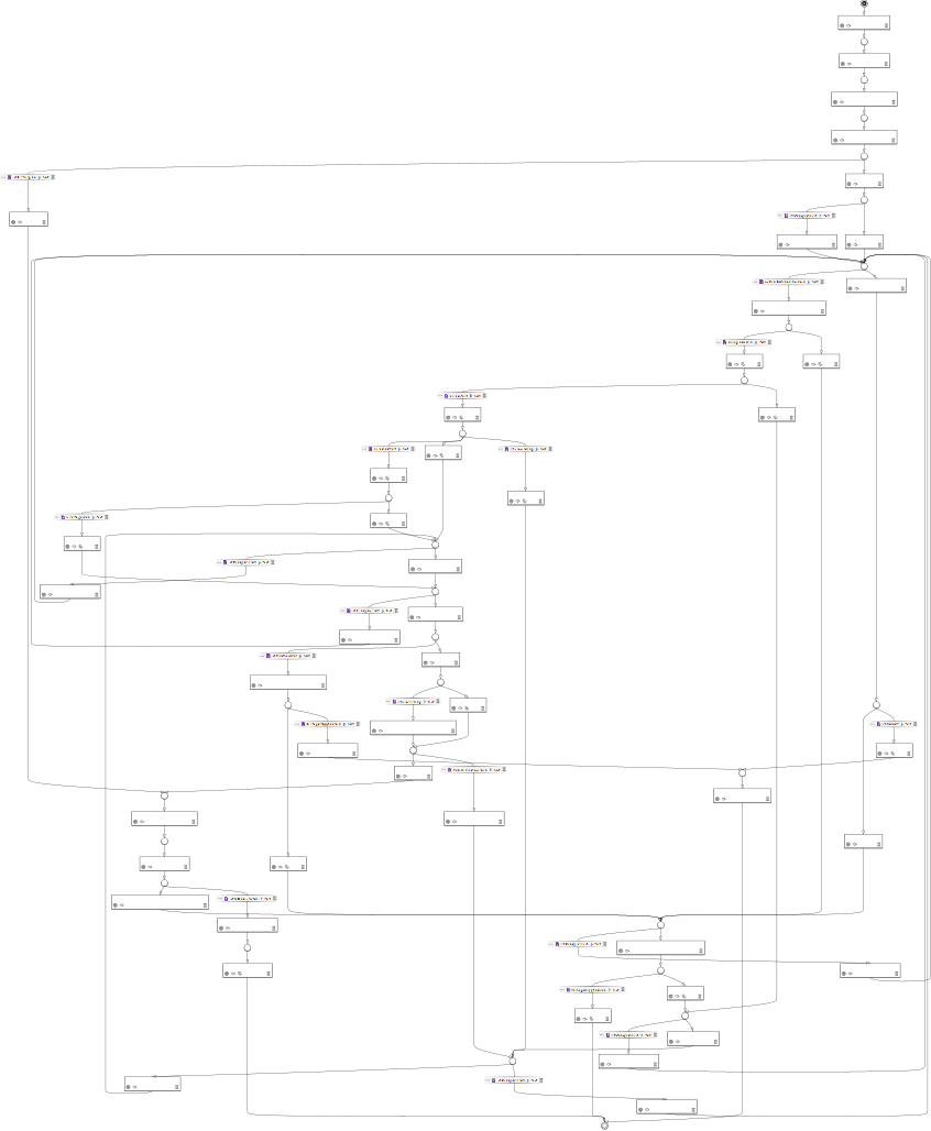 long edge node positions without fix, drawn with GraphViz from LayeredGraph
 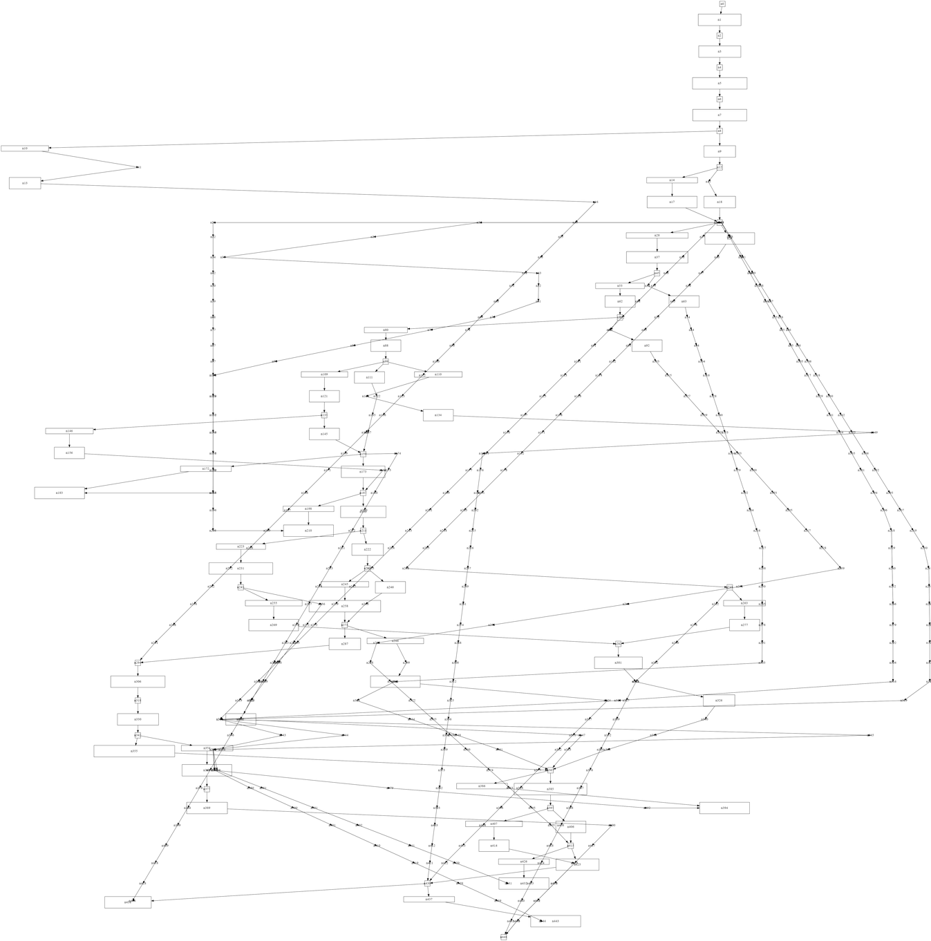 Result layout without fix
 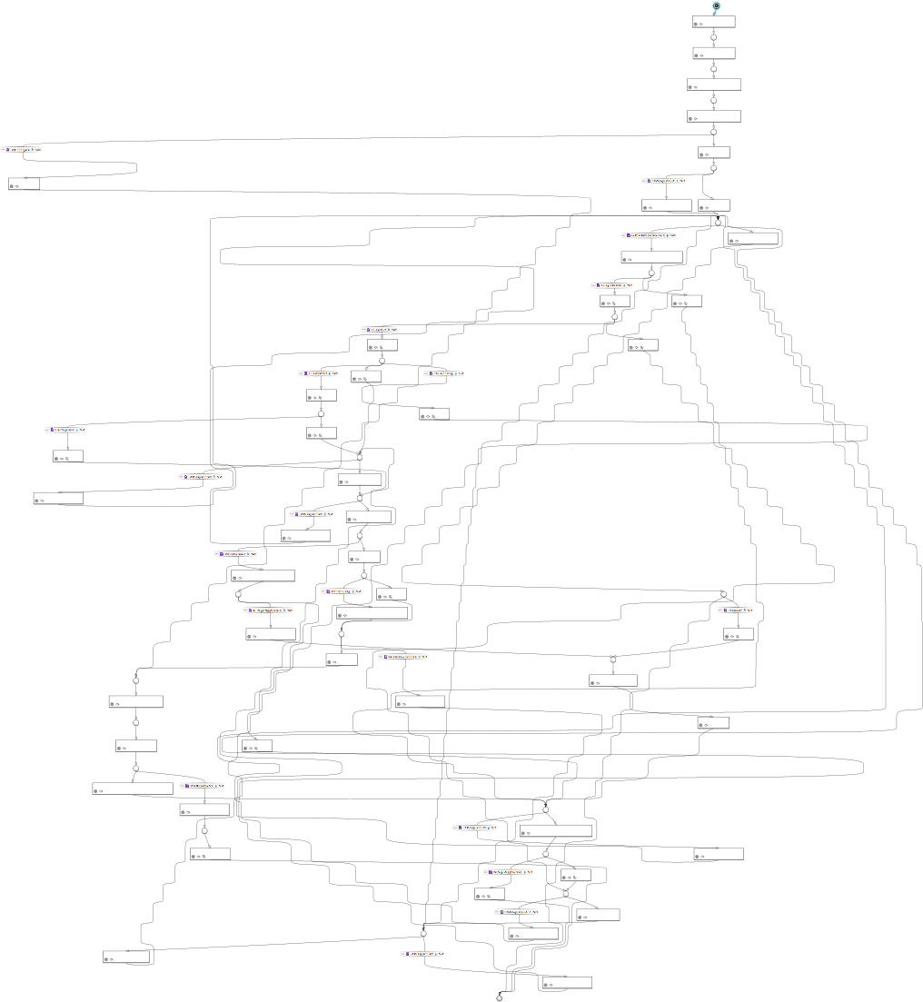 dummy nodes with fixes
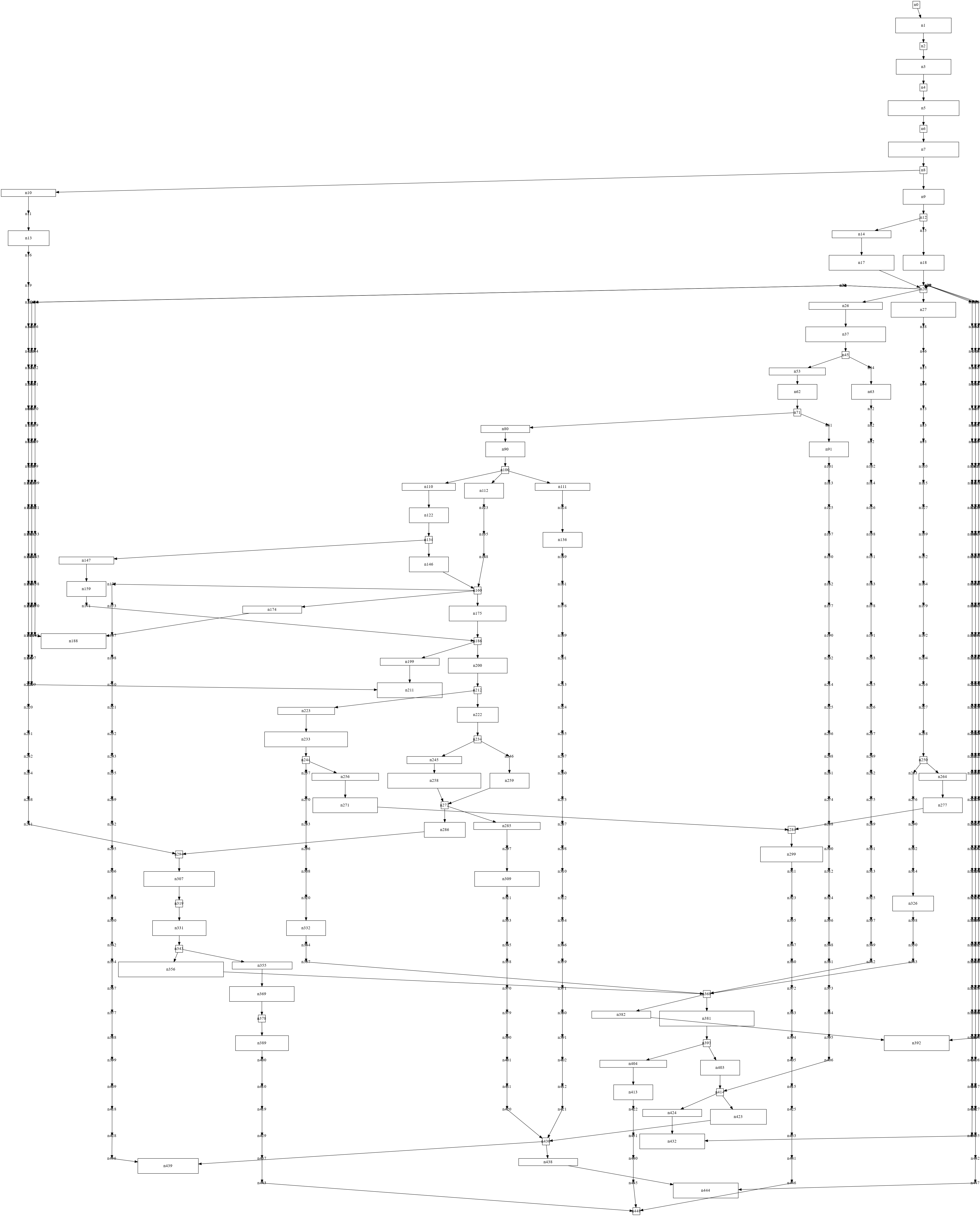
There are still some minimal changes to the layout, but this much is fine. I hope this illustrates why I opened the tickets.
On a sidenote: new long edges that didn't have bendpoints are still looking like a staircase after an interactive layout (as shown above). This happens because InteractiveCrossingMinimizer interpolates the y position between the start- and endpoint. @soerendomroes do you have an idea how to improve this?