WiFi Scan shows channel -4 on 2.4ghz nodes at 5mhz channel width
When running a 2.4ghz node at 5mhz channel width, the WiFi Scan table shows an entry for channel -4 even when channel -4 is not in use on the node. It occurs on firmware 3.22.6.0+, whether or not LQM is enabled, and it occurs across manufacturers (gl.inet, mikrotik, & ubiquiti). It also occurs for both single radio and dual radio nodes. iw dev wlanX scan passive reports an entry for channel -4 in its scan results even though channel -4 is not in use.
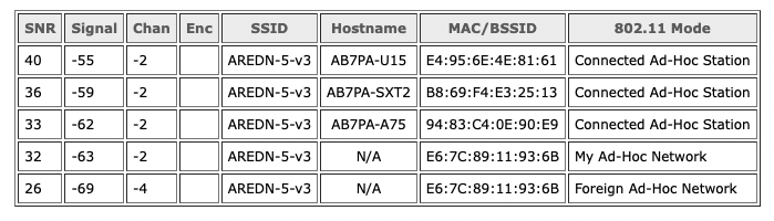
If channel -4 were actually in use, we would expect to see entries for it in the WiFi Scans on other associated nodes, but it does not appear in their scan lists -- leading to the assumption that channel -4 is not actually valid. The channel -4 entry only appears for the node on which the scan is being run. On the example node in the screenshot below, there is an entry for the valid channel -2 as well as an invalid entry for channel -4 having the same BSSID as the valid channel -2 entry. This behavior was not evident on nodes running pre-PR#390 code, but it's not clear whether there is any correlation.
We're fairly sure this isn't an artifact of the spectral scan display as other things line up correctly. Also, the passive scan is detecting the beacons on -4. It's unclear how long this has always been going on as, before 22.6, channel -4 wasn't accessible so the a node probably couldn't detect or report the signal.
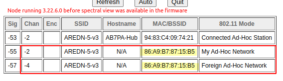
Agree... it was happening on 3.22.6.0 before the Spectral View was introduced. So the Spectral View only served to highlight the issue visually.
This screenshot is from a node running 3.22.6.0, and it shows the channel -4 entry even before the Spectral View was introduced into the firmware.
Please upload the support data -- specifically what the iw scan returns to show this signal on ch -4. The fact that we are seeing the same BSSID is a red flag -- this MAC like # represents the given 802.11 adhoc network that all the devices communicating are connecting to, then each station has it's own MAC address on this ad-hoc network. A given ad-hoc network can't be simultaneously on 2 channels. There may be multiple issues here: A) the scan for ch -4 and ch -2 are really the same thing; B) there could be another device (wireless phone handset, etc.) that spectra data is finding.
What do other locations find? Do both the foreign ad-hoc network and the spectra scan data on ch -4 (which is not a alias of another signal) show up? Just one of the two?
IW scan results: iw-scan.txt
As mentioned above, other nodes scanning on 5mhz channel widths do not see channel -4 on this node -- they only list a channel -4 entry for their own node. If the channel -4 entry was from a different device (wireless phone, etc) then it should have a different BSSID. As you said, same BSSID is a red flag -- and other nodes never see two entries for that BSSID in their scans.
Seeing the phantom -4 listing on a Nano XW 2Ghz, but little energy even in this heavily polluted RF environment. 5MHz wide here as well.
Since the WiFi Scan results are simply the web presentation of the iw dev wlanX scan passive command, the question of root cause seems to be “What is causing the iw results to contain a bogus channel?”
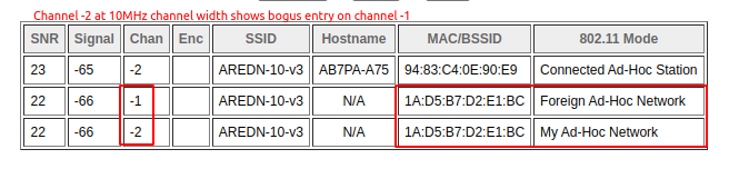
Switching my 2.4ghz nodes to 10MHZ channel width also produces a bogus entry in the table for channel -1 as shown below. It should not be possible to have two channel widths in use on a single BSSID.
@pmilazzo Paul reported last night that during his testing the root cause of the bogus scan table entries appeared to be related to collocated node proximity -- possibly receiver overloading. Paul can elaborate more on his discoveries. Thanks, Paul!
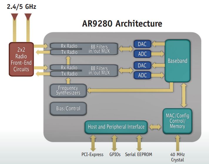
@pmilazzo if you lower the power way down on the co-located nodes, do the symptoms go away? Theoretically, I'm trying to understand how the receiver could decode the signal on a different channel. The frequency is mixed down to a 'baseband' inside the chips. This baseband signal ("BB" in the chip architecture just before analog/digital conversions) would have to bleed through from chip to chip. Not sure if there's any other way to explain this.
Joe:
@pmilazzo https://github.com/pmilazzo if your lower the power way down on the co-located nodes, do the symptoms go away?
Not entirely, but they're much less frequent.
Theoretically, I'm trying to understand how the receiver could decode the signal on a different channel. The frequency is mixed down to a 'baseband' inside the chips. This baseband signal ("BB" in the chip architecture just before analog/digital conversions) would have to bleed through from chip to chip. Not sure if there's any other way to explain this.
I've been asking myself the same question, and I don't really have a great answer. One possibility is some sort of intermodulation distortion, or perhaps the receiver front end is overloaded to the point of clipping, leading to many images of the signal appearing across the band.
Here are some test results from two collocated AR300M16-Ext nodes, K3PGM-26-77-172 and W3DRA-27-208-294:
With K3PGM-26-77-172 transmitting at +23 dBm, we see lots of bogus signals on W3DRA-27-208-294:
(FYI, there are nearby Part 15 devices operating on Channels 6 and 11 with 20 MHz bandwidth but currently with very low traffic; the above scan was done at 10 MHz bandwidth, so you can see it capturing the lower half of the spectrum of a nearby transmission on Channel 6.)
When I turn the transmitter on K3PGM-26-77-172 down to +1 dBm and stick a small piece of metal screen between the nodes, the number of bogus signals drops significantly, but sometimes I still see them. Note that the reported signal level from K3PGM-26-77-172 is exactly 22 dB lower than before.
So, then I realized that my cell phone was sitting on the desk right next to W3DRA-27-208-294, so I moved it to my other desk. Now the bogus signals are even less frequent, and when they appear, they're ~20 dB weaker, which lends some support to the intermodulation-distortion hypothesis.
- Paul, K3PGM
"One possibility is some sort of intermodulation distortion" or clipping.
The 64 subcarriers across the 10MHz channel in 2GHz would have to (mostly) all be precisely and linearly shifted to another channel for the radio to to be able to decode and reassemble the data stream. I just don't see how this could happen -- too much distortion occurring. This baseband frequency is common across all radios -- It would be like an analog Intermediate Frequency being the same across 2 radios and the signal bleeding across. But all this should be highly shielded inside the chip.
If the distance can be slightly increased, to be out of near field, and power dropped, then if these symptoms go completely away, then we'd be able to establish cause and effect.
Well, I've done the experiment, but I'm not sure how to interpret the results.
First, the setup involves two GL-AR300M16-Ext nodes running Nightly Build 1580-665fa49; these are designated:
- W3DRA-27-208-194 ("Ebright-Tunnel")
- K3PGM-26-77-172 ("Test300")
W3DRA-27-208-194 remained fixed while K3PGM-26-77-172 was moved about on a TV tray table. These nodes were positioned first in each other's near field, with both transmitters set to +23dBm:
and showed a predictably strong signal:
Later, K3PGM-26-77-172 was moved to the far field (here I decided upon a literal interpretation of "far field"):
In the near-field test, a scan on K3PGM-26-77-172 showed many false entries, which varied with each successive scan, but as they all have the same BSSID they're not really foreign networks:
Next, K3PGM-26-77-172 was moved to the "far-field" location, with the same transmit-power settings. Some scans now showed no false entries, but many included an entry for Channel -1; the reported signal level from W3DRA-27-208-194 dropped 24dB:
Next, I reduced the transmit power on W3DRA-27-208-194 from +23dBm to +13dBm; the transmit power of K3PGM-26-77-172 was not changed. The false Channel -1 entry still showed up in some scans, but less frequently; the received signal from W3DRA-27-208-194 dropped another 11--12dB:
Across many additional scans, the reported signal level of the Channel -1 signal varied, but was almost always within several dB of the W3DRA-27-208-194 signal level.
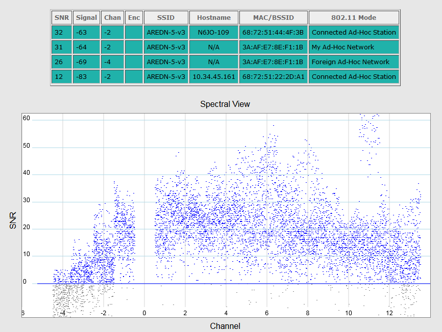
So, I'm not sure what these results mean, but I remain convinced that the scan is somehow reporting signals on the wrong frequencies. For example, the Spectral View in the following scan shows a large burst of energy between the -1 and 0 channel markers. There is no reason for there to be any significant energy there; it's below the Part 15 band and above the 10 MHz signal centered on Channel -2:
Perplexedly,
- Paul, K3PGM
On 7/25/2022 6:28 PM, Joe AE6XE wrote:
"One possibility is some sort of intermodulation distortion" or clipping.
The 64 subcarriers across the 10MHz channel in 2GHz would have to (mostly) all be precisely and linearly shifted to another channel for the radio to to be able to decode and reassemble the data stream. I just don't see how this could happen -- too much distortion occurring. This baseband frequency is common across all radios -- It would be like an analog Intermediate Frequency being the same across 2 radios and the signal bleeding across. But all this should be highly shielded inside the chip.
If the distance can be slightly increased, to be out of near field, and power dropped, then if these symptoms go completely away, then we'd be able to establish cause and effect.
Message ID: @.***>
Fixed in https://github.com/aredn/aredn/commit/8bed661fca24626d2c6a27778d329038a1e5f8c0