Add Longitudinal Rotation of Lane Boundaries
Added roll parameter to boundary point, enables longitudinal rotation of lane boundaries (necessary for boundary points with a specified height and/or width parameter).
Check the checklist
- [x] My code and comments follow the style guidelines and contributors guidelines of this project.
- [x] I have performed a self-review of my own code.
- [ ] I have made corresponding changes to the documentation.
- [ ] My changes generate no new warnings.
- [ ] I have added tests that prove my fix is effective or that my feature works.
- [ ] New and existing unit tests / travis ci pass locally with my changes.
Outcome from the discussions within the Harmonisation-Group meeting (05.11.2020 & 12.11.2020):
- the general intention of the data-field "roll" is not clear
- the descripion "longitudinal axis" can be interpreted in both direction (previous or next BoundaryPoint), whereby also the direction of the angle changes
- a more general description of the fields width, height, roll. Here the definiton "message Dimension3d" (width and hieght), "message Orientation3d" (roll) and "message Vector3d" (direction, can be longitudinal or whathever) defined in osi_common.proto should be discussed.
Output from CCB meeting - 09.12.2020
Actions:
- Further discussions to be conducted in the Harmonization WG and decide what should be included in milestones V3.3 and V4.0.
Some issues with the proposal that came up in discussions were the lack of definition of the corresponding roll axis and what underlying “surface” the roll parameter refers to (e.g. what means roll=0?). Should we define the roll axis as the line between the current BoundaryPoint and its successor in direction of definition of the points?
And how is the height parameter defined? For example, it could be defined along the roll direction (1) or as the vertical height based on the global coordination system (2) or some other reference. Without a roll parameter though, it is even less clear, what the height is supposed to say or what it refers to.

Also, how are specific LaneBoundary types defined when it comes to width and height in general? The BoundaryPoint height description and corresponding picture do not clearly specify how the width is supposed to be set or if it is allowed to be set at all (same with height in case of lane markings). As far as I interpret the documentation, the width in such cases is supposed to be set to 0. In that case the roll parameter could describe an angled curb stone or even a sloping road edge quite well, but it should probably be explained a bit better.

Another question: Are we allowed to use both width and height parameters together at all? For example, can guard rails be described with both width and height (+ roll) parameters in the BoundaryPoint or should they only contain a height parameter with 0-width and then reference a StationaryObject with limiting_structure_id if a more detailed description is needed? I don’t know if it makes sense to refer to lots of StationaryObjects instead of defining the BoundaryPoint a bit more detailed. We should gather some more opinions on that.
I think even (or especially) without the roll parameter many possibilities are not clearly defined yet (especially with a given height). We should discuss what a sensible detail degree of a BoundaryPoint is.
In today’s harmonization meeting, we discussed that it would be good to have a direct comparison of the options. We would like the sensor modeling group to evaluate those. @kmeids
Option 1: Roll rotation based on global coordinate system. Example: When roll = 0, the boundary point height is orthogonal to the global coordinate system
Advantages/Disadvantages:
- Explicit and independent definition of the roll angle
- Necessary to explicitly define the roll angle even if it is not needed (e.g. if you just assume that lane boundaries adapt to the road surface like lane markings)
- Consistent with boundary point position, which is also global
Option 2: Roll rotation based on “imaginary” road surface Example: When roll = 0, the boundary point height is orthogonal to the road surface in the current position (for road surface roll calculation e.g. use yaw of line between two successive boundary points to draw an orthogonal line to an adjacent boundary line)
Advantages/Disadvantages:
- Road surface is not defined and would have to be calculated from boundary points of multiple lanes for each boundary point
- Extensive definition necessary; not explicit without a lot of definition on the calculation principle o E.g. How to consider boundaries between multiple differently angled adjacent lanes?
- No easy precise definition, because the angle depends on the density of boundary points of the lane boundaries
- Roll only needs to be modified if lane boundaries differ from the expectation (only if deviations from the exact value are ok; see previous point)
- Consistent with yaw and pitch, which can more easily be derived from predecessor/successor boundary points (Though, this is not clearly defined yet as well!)
There are different uncertainties related to laneboundaries in OSI, especially regarding their height and width. In my opinion the laneboundary height and width should be understand as the following:
Width and height of laneboundaries are objectparameters:
- they refer to the object itself and not to global coordinates, e.g. a line has a certain width independent from its course
- typical laneboundary objects like lines, curbstones, guardrails, etc. are aligned with the road surface, thus the height refers to the axis perpendicular to the surface
- the normal vector necessary for a transformation into global coordinates can be calculated by triangulation between the laneboundary- (and also centerline-) points if needed
- the discretization of points may be adapted in the OSI data if the discretization for the triangulation is too rough to satisfy specific use case, e.g. visualization purposes
For complex geometries, like noise barriers, fences, special guardrails etc. OSI provides the possibility to reference single stationary objects, which can be parameterized in a detailed way with complete pose and contourline information. This way of describing laneboundaries can always be chosen if laneboundaries have to be described in a very detailed way for specific use cases.
Since it is possible to derive the surface via the laneboundary- (and also the centerline-) positions and it is possible to describe complex geometries of laneboundaries with structure ids if needed I would prefer not to extend the laneboundaries definitions in general by a roll angle, which is only needed for special situations (and is also an approximation though which has to be defined clearly).
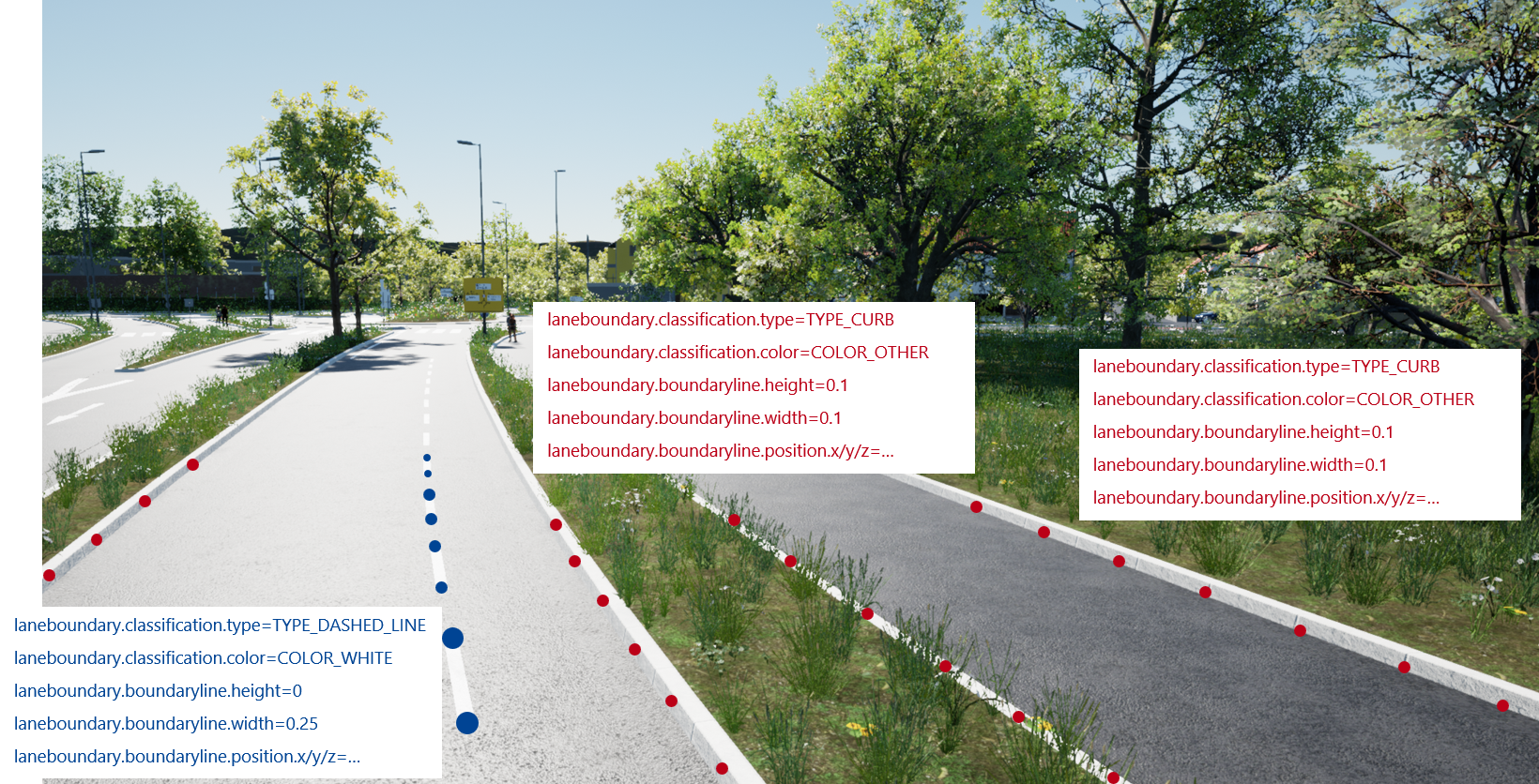
Here are some examples how typical situations could be described with the existing definitions (please note that these examples should support a general idea, so the positions, values, discretizations etc. are not exact):


Additional opinions are appreciated; also gladly with concrete examples ;-)
OSI CCB: @HendrikAmelunxen Can you please give a timeline for this issue? 3.4 is quite imminent. Or is this something for a 4.0 release?
@stefancyliax This is a bigger topic and directly related to the new roadmodel; thus nothing for v. 3.4.
@HendrikAmelunxen, @thomassedlmayer would this still make it to 3.5 or is it directly handled by the Road model, i.e. 4.0?
@kmeids @thomassedlmayer This is nothing that can be handled by harmonization for 3.5. I hope that this handled by the surface lines features, but not sure about this. Thus setting the milestone to 4.0